About hdi pcb by CAMTECH PCB


download 22
Spread the love

Picture5 3

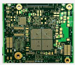
About the reliability of HDI printed circuit boardsHDI printed circuit boards are printed circuit boards with a high routing density per unit area ( High D ensity Interconnect ) compared to “normal” printed circuit boards with CAMTECH PCB. They feature smaller grid, line and gap sizes, smaller hole sizes (laser micro-holes), smaller build and pad sizes, and are characterized by high performance thin materials. This increased density gives more functionality per unit area of ​​the board.

Picture6

High-tech HDI boards include multiple layers of stacked copper-plated micro-vias that form a complex structure. These complex structures provide essential routing solutions for today’s high-pin count ICs used in mobile devices and other high-tech products. The reliability of HDI boards is directly affected by the quality of the copper connections and the base material. Copper connections are tested on a special test sample – coupon, ( coupon ) through thermal cycling, using a special technique – IST ( Interconnect Stress Test ). The coupon is made in the same factory and has the same characteristics as the corresponding printed circuit boards: the same design, copper weight characteristics, hole sizes, mesh sizes and copper coating. The coupon goes through at least 500 thermal cycles, or until it gets damaged, leading to an increase in resistance of at least 10%, which occurs due to the formation of microcracks in the copper joints of the coupon due to thermal effects.Possible damage to the base material is determined by measuring the capacitance between coupon layers before and after testing. The measurement results are compared. A capacitance change of 4% or more indicates significant damage to the material.The loss of reliability of hdi pcb boards is primarily due to the use of lead-free assembly technology. It is produced at a temperature of about 260°C, while the FR-4 material has a limited temperature exposure range. Thermal expansion of the material along the vertical component at such temperatures causes stress “tension” of copper joints. As a result, it leads to microcracks in the central zone of through metallized holes. If the board remains functional after 500 thermal cycles when tested up to 150 ° C, the test sample is considered as a reliable coupon, that is, it passed IST.Failure of the couponThe failure of the coupon with the number of thermal cycles less than 350 is associated with a violation of the technological process, especially in terms of the thickness of the copper plating. A thin layer of copper is precisely the cause of such cracks. In metalized through holes, performance failures can also be due to cracks of another type – corner or “separation” of joints.Micro holes are tested at 190°C. At this temperature, they must withstand at least 500 thermal cycles; in low-quality micro-holes, damage will begin to be fixed much earlier. The most common type of damage is separation of the connection between the pinhole base and the target pad. In second place is the formation of cylindrical cracks inside the base.HDI printed circuit boardsThe reliability of HDI printed circuit boards is also determined by the type of construction. A stacked micro-via design is almost four times more “sensitive” to failure than a staggered design. Well-made one- or two-layer micro-holes practically do not have early failures. Boards with three or more micro-vias stacked on top of each other are very likely to fail IST at 190°C and will therefore have manufacturing problems.Layers during testingAs already mentioned, damage to the material in the IST coupon is assessed by the change in capacitance between layers during testing. The main types of damage are: adhesive delamination – delamination of laminated surfaces, manifested mainly at mesh sizes greater than 1 mm, cohesive cracks – destruction of the epoxy base due to high temperature during installation for a mesh of 0.8 mm and hairline cracks – delamination between fiberglass and epoxy base at 0.5 mm mesh .In conclusion, we can say that the use of lead-free assembly technologies for printed circuit boards with HDI is a serious task associated with the problem of high-quality fabrication of such structures. It is clear that it is necessary to carefully test the compounds and material in order to confirm the reliability of the resulting product. 

See also  The Benefits Of Satellite Tracking For The Logistics Industry
About hdi pcb by CAMTECH PCB   About the reliability of HDI printed circuit boardsHDI printed circuit boards are printed circuit boards with a high routing density per unit area ( High D ensity Interconnect ) compared to “normal” printed circuit boards with CAMTECH PCB. They feature smaller grid, line and gap sizes, smaller hole sizes (laser micro-holes), smaller build and pad sizes, and are characterized by high performance thin materials. This increased density gives more functionality per unit area of ​​the board.High-tech HDI boards include multiple layers of stacked copper-plated micro-vias that form a complex structure. These complex structures provide essential routing solutions for today’s high-pin count ICs used in mobile devices and other high-tech products. The reliability of HDI boards is directly affected by the quality of the copper connections and the base material. Copper connections are tested on a special test sample – coupon, ( coupon ) through thermal cycling, using a special technique – IST ( Interconnect Stress Test ). The coupon is made in the same factory and has the same characteristics as the corresponding printed circuit boards: the same design, copper weight characteristics, hole sizes, mesh sizes and copper coating. The coupon goes through at least 500 thermal cycles, or until it gets damaged, leading to an increase in resistance of at least 10%, which occurs due to the formation of microcracks in the copper joints of the coupon due to thermal effects.Possible damage to the base material is determined by measuring the capacitance between coupon layers before and after testing. The measurement results are compared. A capacitance change of 4% or more indicates significant damage to the material.The loss of reliability of hdi pcb boards is primarily due to the use of lead-free assembly technology. It is produced at a temperature of about 260°C, while the FR-4 material has a limited temperature exposure range. Thermal expansion of the material along the vertical component at such temperatures causes stress “tension” of copper joints. As a result, it leads to microcracks in the central zone of through metallized holes. If the board remains functional after 500 thermal cycles when tested up to 150 ° C, the test sample is considered as a reliable coupon, that is, it passed IST.Failure of the couponThe failure of the coupon with the number of thermal cycles less than 350 is associated with a violation of the technological process, especially in terms of the thickness of the copper plating. A thin layer of copper is precisely the cause of such cracks. In metalized through holes, performance failures can also be due to cracks of another type – corner or “separation” of joints.Micro holes are tested at 190°C. At this temperature, they must withstand at least 500 thermal cycles; in low-quality micro-holes, damage will begin to be fixed much earlier. The most common type of damage is separation of the connection between the pinhole base and the target pad. In second place is the formation of cylindrical cracks inside the base.HDI printed circuit boardsThe reliability of HDI printed circuit boards is also determined by the type of construction. A stacked micro-via design is almost four times more “sensitive” to failure than a staggered design. Well-made one- or two-layer micro-holes practically do not have early failures. Boards with three or more micro-vias stacked on top of each other are very likely to fail IST at 190°C and will therefore have manufacturing problems.Layers during testingAs already mentioned, damage to the material in the IST coupon is assessed by the change in capacitance between layers during testing. The main types of damage are: adhesive delamination – delamination of laminated surfaces, manifested mainly at mesh sizes greater than 1 mm, cohesive cracks – destruction of the epoxy base due to high temperature during installation for a mesh of 0.8 mm and hairline cracks – delamination between fiberglass and epoxy base at 0.5 mm mesh .In conclusion, we can say that the use of lead-free assembly technologies for printed circuit boards with HDI is a serious task associated with the problem of high-quality fabrication of such structures. It is clear that it is necessary to carefully test the compounds and material in order to confirm the reliability of the resulting product. 

Spread the love

Abhay Singh

Abhay Singh is a seasoned digital marketing expert with over 7 years of experience in crafting effective marketing strategies and executing successful campaigns. He excels in SEO, social media, and PPC advertising.